• If you need help identifying a pepper, disease, or plant issue, please post in Identification.

Arduino setup

sorry for all the posts recently.
 
I thought I would share a project I did for my wife. I think it would translate well to hydro. The problem was we bought a new house and the bedrooms didn't have lights. They had a switch for an outlet. On the ceiling they had fans which were operated by a chain. The outlet connected to the switch was in a stupid spot. So I made a radio controlled extension cord. Now she can place the light where she wants and turn the light on and off with a remote. I'll talk hardware first and then talk about code.
First the receiver. This is important because it shows you how to use an arduino to control 110.
parts:
1. Arduino UNO :Control logic and read the receiver http://www.amazon.com/Atmega328p-Atmega16u2-Version-Board-Arduino/dp/B00SF28U7A/ref=sr_1_5?s=pc&ie=UTF8&qid=1431745732&sr=1-5&keywords=arduino+Uno
 
2. Radio Transceiver: receives radio signal http://www.amazon.com/nRF24L01-Wireless-Transceiver-Arduino-Compatible/dp/B00E594ZX0/ref=pd_sim_147_1?ie=UTF8&refRID=0H4YXH7Y9HJJ301MSV7A
 
3. Relay board: turn the 5 volt logic signal to 110 v   http://www.amazon.com/Docooler%C2%AE-Active-Channel-Module-Arduino/dp/B00G9TQH8U/ref=sr_1_7?s=electronics&ie=UTF8&qid=1431745874&sr=1-7&keywords=relay+board
 
4. perfboard wire it all up. Not necessary!
 
I'll get a little more detail into wiring late but look up how to wire the transceiver do a search for nrf24 and you will find videos wiring diagrams etc. Next when you right the code you will send a high signal to the relay board again I'll talk more on wiring later.
 
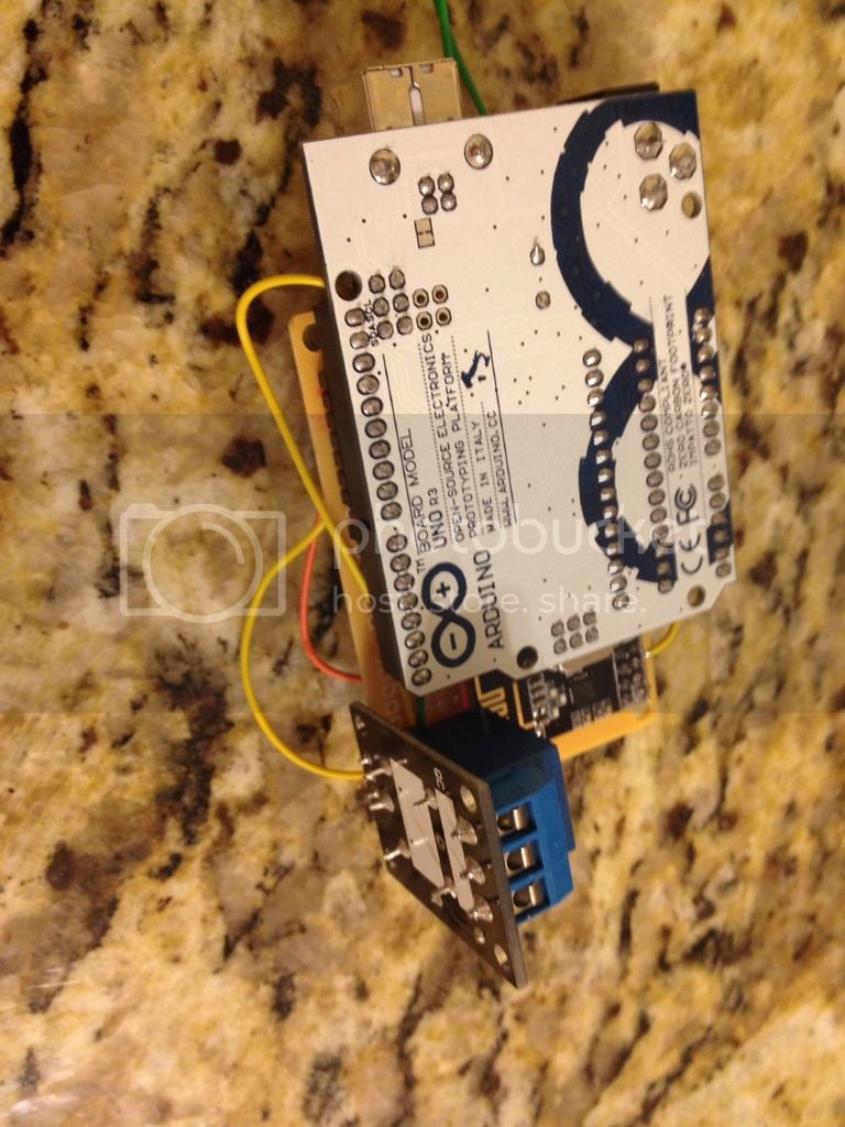
Here is what everything looks like wired up

 
Really you probably don't want a radio controlled plant waterer, light timer, water pump, temperature controller etc. The arduino is easy to code to read inputs and control outputs. The problem is the documentation on controlling 110 or wall outlet power with an arduino is not well documented. As we go on I'll write some simple code to show you how toread and  control things without the radio.
 
That's it for now.


Lets start with relay boards. Don't mess with anything else for wall power. Notice that I am saying relay BOARD not relay. Get the whole board.
 I ordered a relay board and when I get it I'll send some more pictures. A relay board  is just a way to turn off and on 110 volts. It is a switch What turns the power on and off is a five volt input. That input will come from the arduino.
 
There are three pins on a relay:
vcc
Input
ground.
 
To control the relay board, wire the vcc to 5v; the ground to ground and then the input to whatever pin on the UNO you want to control the relay board with.
Next is the "switch" side. In the relay board I used it was from left to right:
normally open
common
normally closed
 
on the extension cord I cut one of the two wires an stuck one end in the common side and another in the normally open side. That's it

 
Let's say I want to have a light go on for eight hours and then off for eight hours. I would wire five volts  and ground from the uno to the relay board and wire pin 13 to the input on the relay board. Wire up the light like I show above and run this code:
int lights=13;
void setup(){
  pinMode(lights,OUTPUT);
}

void loop(){
 
  digitalWrite(lights,HIGH);
  delay(28800000);
 
  digitalWrite(lights,LOW);
  delay(28800000);
 
}
 
 
Edit: listen to me at your own risk. I am not an electrician or engineer. My qualifications are that my house has not burned down and I have all my fingers.
 
To keep this going I'm going to try to post everyday. The length will be determined by the amount of time I have. Which today is about 5 minutes. First the distance you can transmit inside a house is roughly 40 feet. Not very far. To get further you will need one of these as a transmitter:
http://www.amazon.com/Neewer%C2%AE-NRF24L01-Wireless-module-Antenna/dp/B00H6ZO5Y4/ref=sr_1_5?ie=UTF8&qid=1431911139&sr=8-5&keywords=nrf24
 
for the receiver you can still use a cheaper version.
 
Finally I'll explain the code above
 
This just says the pin to control the relay board is 13. I made up the name lights and everywhere in the code where you see it just think "13". 
int lights=13;
 
void setup() just means that this portion runs once and doesn't return a value. Whatever is in between {}  runs just once.
 
  pinMode(lights,OUTPUT);<-This says that pin 13 is going to go to 5v or ground depending on what you program it to do. The alternative is input.
 
 
void loop(){} <- everything between {} runs over and over again... forever.
 
digitalWrite(lights,HIGH); <- make pin 13 put out 5v and in this case turn the relay or light on
  delay(28800000);<- This says don't do anything else for 8 hours. This is in milliseconds. 1000 mileseconds in a second. 60 seconds in a minute. 60 minutes in an hour. for 8 hours. 1000X60X60*8=28800000
 
 
digitalWrite(lights,LOW); <- make pin 13 put out 0v. Turn the relay off.
 
 
Pretty simple huh?
 
Okay last post about relay boards. The reason I spent so much time on them is that they are very useful and I frankly feel there is not enough said about them.
Here are the relays I ordered:

 
This is the side you wirethe light to.  One end to com and one end to NO (Normally Open). See my earlier post for a picture.

 
Now you need to wire up the 5v (yellow) ,ground (black) and IN (orange) to the relay

 
Now wire the IN to the number 13 pin

 
Now wire up the 5v and the gnd

 
If you have wired the relay to a light , powered the Arduino and uploaded the code you now have a light that turns on for 8 hours and then off for 8 hours
 
https://www.youtube.com/watch?v=_LCCGFSMOr4&list=PLA567CE235D39FA84&index=2
 
Short answer is PWM (pulse width modulation). It basiclly turns the fan on and off quickly to control speed. This is better than a resistor because a resistor will reduce current and may not be enough current for the fan.
 
Here is the deal you don't have a fan that operates on the 5 volts and current that the arduino provides. So you have two (or more) choices a transistor like is used in the video or a SOLID STATE relay board. A normal relay board will burn up at those frequencies
 
read the power source (wall wart) of the fan it will say output 12 v dc. Try to get a transistor that seems to foot the bill. Give it a try. If it doesn't work you shouldn't be out too much money and can switch to a solid state relay board
http://www.amazon.com/CTYRZCH-Channel-Module-Arduino-Raspberry/dp/B00R5GHVH2/ref=sr_1_15?ie=UTF8&qid=1431994962&sr=8-15&keywords=arduino+solid+state+relay+board
This code should go high speed for 8 hours and then low speed for 8 hours then highspeed.....
int fan= 13;    
int fanspeed1=255;
int fanspeed2=100;
void setup()  {
 
}
 
void loop(){
 
   analogWrite(fan, fanspeed1);
  delay(28800000);
 
  analogWrite(fan, fanspeed2);
  delay(28800000);
 
}
 
 
You'll need to play with the values of fanspeed to get the right speed the max value is 255 (full power all the time) to 0 (no power any of the time)
 
I have never done this with anything more than 5 v so I can't tell you how well it will work. Maybe if you tell us what the power adapter says is the output someone can tell you what Transister to use
 
I didn't read the whole thing but this might also help. My advice start with an led to make sure you have the program and everything right. Once satisfied then try to find the right transistor.
https://itp.nyu.edu/physcomp/labs/motors-and-transistors/using-a-transistor-to-control-high-current-loads-with-an-arduino/
 
These are my fans:
 
4"
 
FNC_FG4XL.jpg

 
8"
 
Hyper-Fan-8-inch-710-CFM-Fan-With-Digital-Controller-701405.png


Yes. The blue one is awesome.
 
Blue fan is pretty sick looking. I don't remember what brand fan is sitting on my filter. I just know my speed controller is stuck in my outlet. For life of me I can't get it out. Not that I really need to but I tried to move it last night and I couldn't unplug it. Damn controller started to pull apart. 
 
D3monic said:
Blue fan is pretty sick looking. I don't remember what brand fan is sitting on my filter. I just know my speed controller is stuck in my outlet. For life of me I can't get it out. Not that I really need to but I tried to move it last night and I couldn't unplug it. Damn controller started to pull apart. 
 
lol does it screw in?
frosty said:
yeah no way i'm going to tell you how to screw up a nice fan like that.
 
Moves a ton of air.
 
Oh I'm pretty schooled in electronics/electricity.
 
Alright my guess is that the dial on the control is a potentiometer you might  look at it and see if you can replace it with a digital pontentiometer and control it with the arduino. Otherwise you can check max and min voltage and use the transistor method in the video.
Let's wire up the Transmitter.
You can get the wiring pattern and other helpfull hints from here.
https://arduino-info.wikispaces.com/Nrf24L01-2.4GHz-HowTo
We will use the RF24 library so you will want to use that pattern. Take your time and make sure you understand the orientation of everything. I use jumpers with a female end and a male end like this:

 
I tried to match the wire color recommended in order to avoid any screw-ups I didn't have all the colors but I got close enough

 
We are moving fast now and I expect to be all done in a couple of posts. If you are playing along at home make sure you download the rf24 library.
https://arduino-info.wikispaces.com/nRF24L01-RF24-Examples
We are going to use the led control example.
http://maniacbug.github.io/RF24/led_remote_8pde-example.html
 
The programming is going to be stupid easy. All we do is use our backspace button on the code above.
 
All that is left is wiring up a button with a pull up resistor and wiring up the receiver the exact same way. The hardest part is done
 
i so wanted to do this when i started my seedlings, but after money struggles i decided against it.  i was gonna use a RPI B+  to do cron jobs and push relay scripts (10 on for light, and some form of drip irrigation)  
 
I think people default to the B+ too much. If you look around you can get unopened B's and A's and A+'s. Buying cheap Chinese relays and Arduinos will save you a crapload. Just read the feedback to make sure you are buying a board that can be programmed without any special steps.
 
For reading temps, light blah blah and controlling lights fans etc an Arduino is plenty. A raspberry pi doesn't have analog inputs. This makes reading sensors more difficult
 
Multi channel relay board and an Arduino uno can control all your devices for hydro. The only benefit of the RPi in this case is you can use python.
 
Okay I'm not next to my arduinos right now So we are going to talk code. Read the instructions on downloading the library from:
https://arduino-info.wikispaces.com/nRF24L01-RF24-Examples
Frankly you may have to google how to upload a library to Arduino. I always forget and have to do a search. Open the Arduino IDE and:
1. click Examples
2. click RF24
3. click led_remote
read the comments. Comments have either // in front of them or are after /*. Don't worry about the program it is well written but you have to be fairly familiar with C language to completely get it.
We are only going to control 1 output. Find these lines:
 
// Pins on the remote for buttons
const uint8_t button_pins[] = { 2,3,4,5,6,7 };
 

// Pins on the LED board for LED's
const uint8_t led_pins[] = { 2,3,4,5,6,7 };
 
 
Now change those lines to this:
 
// Pins on the remote for buttons
const uint8_t button_pins[] = { 7 };
 

// Pins on the LED board for LED's
const uint8_t led_pins[] = { 7 };
 
 
That's it
 
Save the code as "Frostys_Radio
What you did was set pin7 to read the button on the transmitter and when you do that pin 7 on the receiver will go to 5 volts turning on the relay.
 
Did you see this part?
// sets the role of this unit in hardware.  Connect to GND to be the 'led' board receiver
// Leave open to be the 'remote' transmitter
const int role_pin = A4;
 
What mean is you take a male end of a jumper wire and plug into a gnd pin on the arduino. Take the other male end and put it in the pin A4. Voila that make it a receiver.  I used a 330 resistor because I feel weird plugging in a straight wire. Probably my own paranoia.
 
I'll show all the wiring when I get to my Arduinos!
 
PS. the wife really likes her remote light.
 
I'm going to get off topic for a second and was poetic about physical computing. It is the best way to learn programming. I really did learn python and linux with a raspberry pi. the feedback loop was quick and that made learning fast. It is more engaging than see "hello world" on a screen. I now use python to automate tasks and do financial simulations at work.
 
There is this concept in my industry called a "unicorn". It is a guy who has business sense, analytical ability and programming ability. I get contacted by headhunters and companies at least once a month. My programming is not strong enough to be a unicorn but they are mythical beasts anyway.
 
Using a raspberry pi, touchscreen, leds and a touchscreen I created a 'quizzer'. I put questions and answers into excel, save on a thumbdrive and plug into the "quizzer" it asks questions. If you make the right choice the screen says good job and blinks lights. The wrong answer and it buzzes and tells you the right answer. The lights got more fancy as my at the time 4 year old son got bored. Now I'm going to have to add a sticker dispenser. Anyway, he knows simple addition, continents, sequences blah blah.
 
actually, i was going to use it cause i had a spare!   i was gonna do something in python to do it, but like i said money and time caught up to me :P      
 
 
i did a project for my capstone class involving temperature monitors and the RPI, i used alot of equipment that relied on ATMEGA 328P and 433mhz radio transmitters.  i couldnt get the thing setup the way i had liked it though :/  was used for data center monitoring, i couldnt get the software that came with it to alarm on thresholds :fireball:  
 
gangaskan said:
actually, i was going to use it cause i had a spare!   i was gonna do something in python to do it, but like i said money and time caught up to me :P      
 
 
i did a project for my capstone class involving temperature monitors and the RPI, i used alot of equipment that relied on ATMEGA 328P and 433mhz radio transmitters.  i couldnt get the thing setup the way i had liked it though :/  was used for data center monitoring, i couldnt get the software that came with it to alarm on thresholds :fireball:  
I looked at the 433s and they are cheap but I get the feeling that controlling for noise and transmitting data is a little tricky. I have never bootloaded or programmed a chip directly I always used an Arduino. Now with prices as low as they are and arduinos as small as they are I see no reason to mess around with chips.
 
Alright here are pictures of the wiring for a transmitter. first is the switch. pictures are hard to see so let me describe in words. On one end of the switch wire to ground. on the other end of the switch put a 10k resistor going to 5v and another wire going to pin 7. you are done. In the picture the yellow goes to 7. The red is 5v and the ground is gray.


Here is the transmitter moved to a perf board and a battery pack added.


Now for the receiver. Wire one pin from ground to the A4 pin. Here I use a 330 ohm resistor because I just have a hang up of wiring pins directly to ground. The purpose of this is to tell the arduino it is a receiver.


I don't have a picture for this but wire the 7 pin to the IN on the relay board. Like I showed above but replace the 13 pin with 7
 
Upload the program to both boards and you are good to go.
 
I realize I left off details like how to get the arduino ide. I don't want to write too much and other people have done a better job than I would. If you try this and have problems put the question here and contact me. I'll try to answer your question. 
 
nice job :)  
 
 
actually programming it was easy, it uses UART and i uploaded the IDE sketches to the device itself.  i'm sure it would be easy to adapt stuff too what i have, but i have little to no experience with arduino programming. 
 
Back
Top